


Filed under: Elektro banget, Mikrokontroller, Uncategorized | 3 Comments »
Update RFid
Posted on 12 April 2010 by darie
 Beberapa minggu yang lalu banyak yang nanya ke saya tentang RFid, kenapa ini sekarang jadi tren karena isunya KTP indonesia akan di buat elektronik(e-ktp) pakai rfid dengan besar memory 4k ini beritanya di detik, saya cari jenis rfid itu di indonesia ada kartu tag mifare sedangkan read/writenya juga ada spec lengkap bisa lihat di sini. kalau menurut detik chip mau di datangkan dari china trus aplikasi dari german, saya cuma bertanya-tanya apa orang indonesia gak ada yang bisa bikin aplikasi yang demikian kenapa harus pakai hasil dari bangsa lain.
Ini sedikit cerita kemarin saya main ke pusat elektronic ada produk c*na RFid reader yang murah tapi tanpa datasheetnya, dan akhirnya saya coba beli, di barangnya cuma ada keluaran kabel 6 buah dan keterangan Red (VCC),Balck (GND),Green(D0/Rx/4r+,white(D1/Tx/4R-,blue (led),yellow(BEEP), saya coba langsung masukan ke laptop dengan usb konverter serial saya lihat hasilnya ternyata gak bisa tampil dan setelah saya cek keluaran dari alat ini Wigend26 saya akhirnya saya buat program untuk konversi wigend26 ke serial dengan keluaran data udah berbetuk text jadi enak buat di olah di program komputer, sekalian saya kasih konveter serial to Usb biar laptop sekarang bisa memakainya. alatnya bisa baca tag jenis id12 dan hasil pembacaanya stabil bagus juga dan murah
semoga tulisan ini bermanfaat
Filed under: Artikel-artikel, Elektro banget, Mikrokontroller, RFid | 3 Comments »
Aplikasi dari innovative-electronics part 5
Posted on 14 Juni 2009 by darie
| AN141 | AN141 | Menghubungkan DT-BASIC Ke Komputer Melalui Port USB Proyek ini akan memanfaatkan PC-Link USBer sebagai modul USB to serial converter untuk menghubungkan DT-BASIC Mini System ke port USB komputer. Kemampuan DT-BASIC Mini System untuk berinteraksi dengan LCD karakter berkontroler HD44780 juga akan ditampilkan dalam AN ini yaitu untuk memvisualisasi data dari komputer. |
20/05/09 | ||
| AN142 | AN142 | Menghubungkan DT-51™ Low Cost Series Ke Port USB Komputer Sebuah contoh lagi dalam penggunaan PC-Link USBer sebagai modul USB to UART converter dengan driver VCP (Virtual COM Port). Dalam AN kali ini, PC-Link USB akan menghubungkan DT-51™ Low Cost series ke port USB komputer. DT-51™ Low Cost Micro System / Low Cost Nano System akan bertindak sebagai ko-prosesor eksternal berantarmuka USB untuk melakukan penjumlahan 2 buah variabel. DT-51 is a trademark of Innovative Electronics. |
20/05/09 |
Filed under: Elektro banget, Mikrokontroller | 1 Comment »
Aplikasi mikrokontroler avr dengan bascom avr part 1
Posted on 13 Maret 2009 by darie
Filed under: Artikel-artikel, avr, Elektro banget, Mikrokontroller, Teknologi | 2 Comments »
Aplikasi dengan program bascom 8051
Posted on 13 Maret 2009 by darie
| sumber : mcselec
BASCOM-8051 |
||||||||||||||||||||||||||||||||||||||||||||||||||||||||||||||||||||||||||||||||||||||||||||||
|
||||||||||||||||||||||||||||||||||||||||||||||||||||||||||||||||||||||||||||||||||||||||||||||
Filed under: Artikel-artikel, Mikrokontroller, Teknologi | 23 Comments »
Tutorial BASCOM
Posted on 23 Februari 2009 by darie
Karena banyaknya permintaan tutorial Bascom maka saya akan coba memberikanya sebenarnya tutorial ini sudah ada kalau anda menginstal software tersebut, yaitu help nya. Disitu semua sudah di jelaskan dengan gamblang bahkan sampai bagaimana membuat downloadernya terus cara konfigurasinya kalau yang belum bisa download file di bawah ini
Filed under: avr, DOWNLOAD, Elektro banget, Mikrokontroller, Uncategorized | 12 Comments »
Download Update Source code Produk Innovative electronics
Posted on 26 Oktober 2008 by darie
|
19/09/2003
|
DT51L under MS-DOS untuk prosesor dengan kecepatan tinggi. Sudah teruji hingga kecepatan 2,4 GHz. Hanya untuk DT-51 MinSys Board versi 3.0
|
||
|
|
04/09/2003
|
DT51D under MS-DOS untuk prosesor dengan kecepatan tinggi. Sudah teruji hingga kecepatan 2,4 GHz. Hanya untuk DT-51 MinSys Board versi 3.0
|
|
|
26/09/2003
|
DT51L under Windows dengan tampilan yang lebih menarik dan mudah dipelajari. Hanya untuk DT-51 MinSys Board versi 3.0
|
||
|
01-04/09/2003
|
Include File AlpNum.INC (penambahan prosedur Clear) dan AlphaSS.INC (memuat rutin untuk interface Synchronous Serial) beserta contoh penggunaannya.
|
||
|
19-26/09/2003
|
File-file tes under MS-DOS untuk DT-51 MinSys versi 3.0.
|
||
|
24/06/2003 (LCD) & 12/07/2003 (PI)
|
Include File PhoneInt.ASM (perbaikan rutin Call Progress) dan DLCDPPI.ASM (perbaikan protokol)
|
||
|
26/12/2003
|
Perubahan beberapa label AlpNum.INC dan AlphaSS.INC yang sama dengan label de KITS Serial RTC & EEPROM
|
||
|
09-10/12/2003
|
Perubahan program testing de KITS Serial RTC & EEPROM
|
||
|
19/04/2004
|
DT51L under Windows versi 2 dengan perbaikan bug, shortcut keys, toolbar, dan kemampuan untuk mengakomodasi USB to Serial Converter (pada DT-51 MinSys Board dengan kernel terbaru). Hanya untuk DT-51 MinSys Board versi 3.0
|
||
|
01/05/2004
|
Perbaikan Keymatic.INC agar tidak mempengaruhi komunikasi de KITS SPC Alphanumeric Display
|
||
|
01/02/2005
|
Perbaikan komunikasi serial pada software tester DT-AVR Low Cost Micro System
|
||
|
29/04/2005
|
DT51L Under Windows versi 2.1 dengan penambahan menu Recently Opened Files
|
||
|
29/04/2005
|
ProgPAL versi 1.1 dengan penambahan menu Recently Opened Files dan kemampuan untuk mengakomodasi USB to Serial Converter (pada DT-51 MinSys Board dengan kernel terbaru). Hanya untuk DT-51 MinSys Board versi 3.0 |
||
| 28/06/2005 |
Software Programmer untuk DT-HiQ Programmer versi 1.1 yang mendukung penggunaan USB to Serial Converter dan tersedia pengaturan delay.
|
||
| 28/06/2005 |
DT51L under Windows versi 2.1b sebagai perbaikan pada Selftest DT51L under Windows versi 2.1.
|
||
| 13/03/2006 |
Update untuk program tester DT-AVR Low Cost Micro System, dapat bekerja pada
OS Windows 98, 2000, dan Windows XP. |
||
|
28/03/2006
|
Update untuk program tester DT-AVR Low Cost Nano System, dapat bekerja pada
OS Windows 98, 2000, dan Windows XP. |
||
| 19/04/2006 |
Program tester DT-51 I2C ADDA yang bekerja pada OS Windows 98, 2000, dan XP.
|
||
| 01/05/2006 |
DT-BASIC System Serial Test v1.1, program serial tester untuk DT-BASIC Mini / Micro / Nano System yang dapat bekerja dalam Windows XP / 2000 dan dilengkapi dengan pengaturan time out.
|
||
| 15/11/2006 |
Program tester I2C ADDA under Windows
|
Filed under: DOWNLOAD, Elektro banget, Mikrokontroller | Tagged: update | 7 Comments »
BUKU DIKTAT KOMUNIKASI DATA
Posted on 14 Oktober 2008 by darie
Pas aku buka-buka artikel-atikel lama saya yang ada di labtop kemudian aku temukan artikel tentang komunikasi data yang lumayan lengkap bagus kalau di gunakan buat belajar tentang komunikasi data.
kalau dari temen-teman ada yang mau bisa di download semoga ini ber manfaat
Filed under: Elektro banget, Mikrokontroller, Teknologi | Tagged: buku | 1 Comment »
Developing for the Atmel AVR Microcontroller on Linux
Posted on 5 Oktober 2008 by darie
January 5th, 2005 by Patrick Deegan in
You’ll enjoy the programming ease and built-in peripherals of the new generation of microcontrollers. Best of all, with these tools you can develop for the popular AVR series using a Linux host.
Whether you are creating a small Internet appliance, some hardware instrumentation, data loggers or an army of autonomous robots to do your bidding, in numerous situations you need the flexibility of a programmable computer. In many cases, a general-purpose system, such as the workhorse sitting under your desk, doesn’t meet size, cost or power-consumption constraints and is simply overkill. What you need is a microcontroller.
This article provides step-by-step instructions for setting up a complete development system for the Atmel AVR series of microcontrollers, using free software and Linux. The detailed instructions provided here will allow you to transform your Linux system into a complete AVR development environment. This article walks you through all the steps of building, debugging and installing a simple program.
When all the electronic components required to make a central processing unit (CPU)—instruction decoder, arithmetic/logic unit, registers and so on—are integrated into a single chip, you have a microprocessor. When, in turn, you bundle this CPU with supporting components, memory and I/O peripherals, you’ve got a microcomputer. Extending the integration and miniaturization even further, you can combine all the elements of a microcomputer onto a single integrated circuit—behold the microcontroller.
The semiconductor industry evolves rapidly, making it difficult to provide an accurate and complete definition of the term microcontroller. Consider this: some microcontroller chips have capacities and clock speeds that surpass the 74KB of program memory and 4KB of RAM available to the 30kg Apollo Lunar Module computer. You can expect today’s screamer PCs to be running tomorrow’s embedded applications, with the definition of microcontroller shifting accordingly.
Microcontrollers all have a microprocessor core, memory and I/O interfaces, and many have additional peripherals onboard. The specific configuration of a particular chip influences its physical packaging, number of pins and cost. If you are accustomed to working with microcomputers, you may feel that microcontrollers are tight spots. They have a handful of kilobytes of program ROM and in the area of 256 bytes of RAM. Don’t fret though; a lot can be done in this space, as the MIT Instrumentation Lab demonstrated when developing the Apollo Lunar Module software that controls its moon landing, return from the surface and rendezvous in orbit.
The AVRs are 8-bit RISC platforms with a Harvard architecture (program and data memory are separate). Figure 1 details the ATtiny26 AVR chip internal organization. Like each member of a family, it has its own particular combination of I/O and peripherals, but it shares a basic architecture and instruction set with all the other AVRs. The ATtiny26 has 2KB of program Flash memory, 128 bytes of onboard SRAM and EEPROM, two 8-bit counters and pulse-width modulators, 11 interrupts, 16 I/O pins spread over two 8-bit ports, an 11-channel 10-bit analog-to-digital converter and more—all on a single tiny 20-pin DIP.
A number of factors make the AVR microcontrollers a good choice, especially for beginners. AVRs are:
- Easy to code for: AVRs were designed from the ground up to allow easy and efficient programming in high-level languages, with a particular focus on C.
- Easy to program: the combination of onboard reprogrammable Flash program memory and the in-system programming interface keeps the process of transferring software to the microcontroller simple and cheap.
- Powerful and inexpensive: AVRs pack a lot of power (1 MIPS/MHz, clocks up to 16MHz) and space (up to 128K of Flash program memory and 4K of EEPROM and SRAM) at low prices. Most AVRs even include additional peripherals, such as UARTs and analog-to-digital converters.
- Hobbyist-friendly: most of the chips in the AVR family come in easy-to-use 8-, 20-, 28- or 40-pin dual in-line packages (DIPs) and can be ordered in unit quantities from a number of distributors.
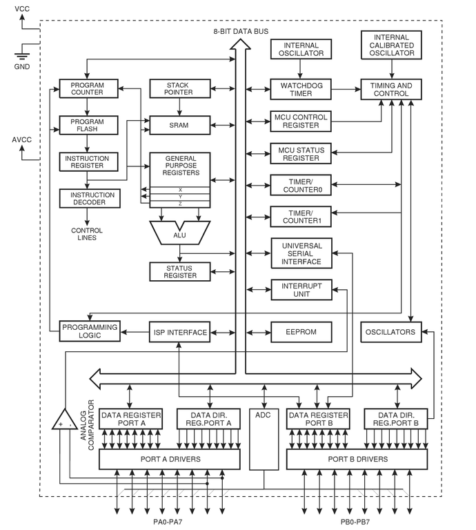
Figure 1. ATtiny26 Block Diagram
The processor core, composed of the components in the upper-left portion of Figure 1, includes elements to read the program memory and to decode and execute the instructions within that memory. The CPU also can fetch and store data to and from the EEPROM, SRAM and the 32 registers. The registers act as extremely efficient storage for 8-bit values (1 byte), and the ALU (arithmetic/logic unit) can operate directly on each of the 32 registers. This AVR features a RAM-based stack. In a few other AVRs, which don’t have any SRAM, the stack is hardware-based, limiting the stack depth to three.
Most instructions take only a single clock cycle to execute, and there is no internal clock division on AVRs. The CPU fetches and decodes the next instruction as it is executing the current instruction. These combined facts mean that AVRs can reach performances of nearly 1 MIPS (million instructions per second) per MHz. With clock rates of up to 16MHz, you can choose the right balance of speed, power consumption and electromagnetic noise for your particular application.
Program space is a contiguous block of Flash memory, 16-bits wide that can be erased/rewritten 10,000 times. You can design your circuit to allow firmware upgrades in-circuit, using in-system programming.
All AVRs have some EEPROM, and most have SRAM; both are 8-bits wide. The EEPROM is designed to withstand at least 100,000 erase/write cycles. EEPROM is useful because it can be written from within your embedded program to retain data, even without a power supply, or during programming, such as for production-line calibration.
All AVRs, from the tiny 8-pin DIPs to the 44-pin Megas, have at least one data port. Data ports allow for input or output of logic-level data. The AVR ports are bidirectional, allowing you to set them for input or output on a pin-by-pin basis.
Many of the AVRs include additional hardware peripherals, such as UARTs for serial communication and calibrated RC oscillators used as internal system clocks. The external pins often serve two or more purposes, and how they are used depends on how you’ve configured the microcontroller. For instance, Figure 1 shows that certain I/O lines from both ports can be used with the multiplexed A/D converter.
The set of tools described here isn’t the only one available, but it allows you to do basically anything, and the tools function well together. The toolkit is comprised of Binutils, GCC, AVR Libc and our Makefile template to write and build programs for the AVR microcontrollers; GDB and simulavr to debug your software; and avrdude as well as a hardware programmer to transfer your software to the microcontrollers. See the on-line Resources for download URLs for all software.
Fortunately, the recent versions of all these tools include support for the AVR platform, so installation is straightforward. We assume you’ve chosen to install everything under /usr/local/AVR.
Download a fresh copy of the current binutils source by following the link in the Resources. Untar the source, move into the binutils-X.XX directory and run:
$ ./configure --prefix=/usr/local/AVR --target=avr
$ make
# make install
The /usr/local/AVR/bin directory now contains AVR versions of ld, as, ar and the other binutils executables. Add the /usr/local/AVR/bin directory to your PATH now. You can apply the modification system-wide by adding:
PATH="$PATH:/usr/local/AVR/bin"
to the /etc/profile file. Make sure the directory is in your PATH and that the change has taken effect before proceeding.
After retrieving a recent release of the Gnu Compiler Collection from a mirror, run the following commands from within the unpacked top-level source directory:
$ ./configure --prefix=/usr/local/AVR \
        --target=avr --enable-languages="c,c++" \
        --disable-nls
$ make
# make install
This builds C and C++ compilers for AVR targets and installs avr-gcc and avr-g++ in /usr/local/AVR/bin.
The AVR Libc package provides a subset of the standard C library for AVR microcontrollers, including math, I/O and string processing utilities. It also takes care of basic AVR startup procedures, such as initializing the interrupt vector table, stack pointer and so forth. To install, get the latest release of the library and run the following from the top-level source directory:
$ unset CC
$ PREFIX=/usr/local/AVR ./doconf
$ ./domake
# ./domake install
The Psychogenic team has created a standard Makefile template that simplifies AVR project management. You can customize it easily for all your assembly, C and C++ AVR projects. It provides everything for a host of make targets, from compilation and upload to the microcontroller to debugging aids, such as source code intermixed with disassembly, and helpful gdbinit files. A detailed discussion of the template is available, and the Makefile template is available as Listing 1 on the Linux Journal FTP site (see Resources). Store the template with the other AVR tools, moving it to /usr/local/AVR/Makefile.tpl.
Using avr-gdb and simulavr in tandem, you can run your software on a choice of AVR microcontrollers through the simulator, while using GDB to step through and observe the executing code. Acquire the simulavr source from the project site and perform the installation:
$ ./configure --prefix=/usr/local/AVR \
  --with-avr-includes=/usr/local/AVR/avr/include
$ make # make install
Install GDB, built for AVR targets, by compiling the source as follows:
$ ./configure --target=avr \
     --prefix=/usr/local/AVR
$ make
# make install
When you finally have a program ready for testing on actual hardware, you need some way to upload the data and write it to the microcontroller’s Flash program memory. AVRDUDE and a compatible hardware programmer are the last components of the development kit. Grab a copy of the AVRDUDE source and install it with:
$ ./configure --prefix=/usr/local/AVR
$ make
# make install
You now have installed every software component required for a complete AVR development environment. All you need is the physical means to transfer programs to microcontrollers.
AVRDUDE supports a number of different hardware programmer configurations. The simplest systems are described on the AVRDUDE site and are comprised of little more than a parallel port connector, a ceramic oscillator and a DIP socket. These are powered directly off the computer’s port and may not work for everyone.
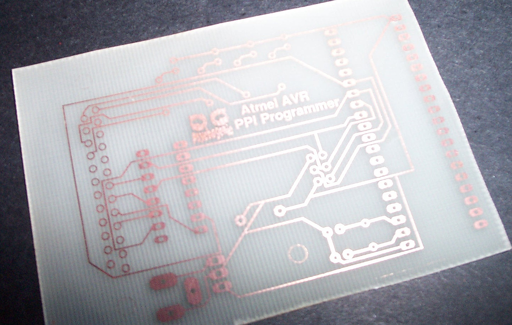
Figure 2. Home-Brew PPI Programmer PCB
A step up in complexity, independently powered, buffered in-system programmers can be built easily (see Resources). Two programmers requiring only a few parts are discussed on the Psychogenic Web page, which describes the schematics, provides artwork and has complete instructions on creating your own printed circuit boards (as depicted in Figure 2) for the programmers.
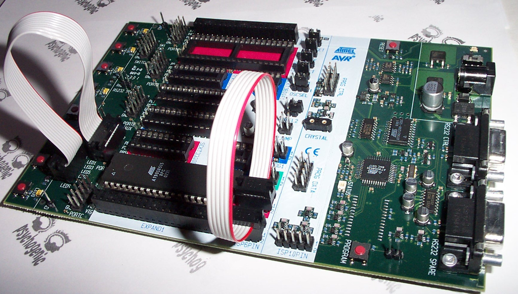
Figure 3. Atmel STK500 Development Kit
A number of commercial solutions also are available. If you’re interested in easily programming a wide selection of the AVR family, go with Atmel’s STK500 kit. More than a simple programmer, the STK500 is a starter kit that allows you to program the microcontrollers and easily prototype new designs. It includes a number of LEDs and switches, an oscillator, RS-232 interface and other niceties that easily can be interfaced with your target chip.
Our focus here is on the development system rather than on programming for the AVR platform. The AVR Libc documentation is a good place to start for information on programming AVRs in Assembly, C and C++.
The Hello World program of the microcontroller universe is the classic flashing LEDs. A slightly different take on this theme, which Knight Rider fans should appreciate, is available on the Linux Journal FTP site, where you can download C (Listing 2) or C++ (Listing 3) versions of an example program that cycles each of eight light-emitting diodes (LEDs) back and forth.
Create a project directory—for instance, ~/helloavr/—and retrieve the program, saving Listing 2 as ~/helloavr/kr.c and Listing 3 as ~/helloavr/kitt.cpp. Also, copy the Makefile template, /usr/local/AVR/Makefile.tpl, to ~/helloavr/Makefile.
Using this Makefile is easy and makes compilation a snap. Open the Makefile in your favourite editor and modify the configuration section, near the top of the file, so that the MCU, PROJECTNAME and PRJSRC variables are set as shown in Listing 4. The MCU variable determines the AVR family member for which we are compiling the program, and the PRJSRC variable lists all the Assembly, C and C++ source files used in the project.
Once you’ve configured the Makefile, compiling and linking the program is as simple as typing make.
You can perform the compilation and linking steps manually instead, by issuing:
  $ avr-gcc -I.  -g -mmcu=at90s8515 -Os       \
             -fpack-struct -fshort-enums               \
             -funsigned-bitfields -funsigned-char \
             -Wall -Wstrict-prototypes -c kr.c

  $ avr-gcc -o helloavr.out kr.o
The most notable difference is the addition of the required -mmcu command-line argument, used to specify the target microcontroller. Either method compiles kr.c and creates the helloavr.out ELF-format program. This file cannot be executed on your development station but is used later during the debugging stage.
You also can build the C++ version of the program by doing a make clean, changing the Makefile PRJSRC variable to kitt.cpp and then issuing another make.
A Makefile target that is interesting, whether for sanity checking, optimization, low-level debugging or simply to get to know the AVR internals, is disasm. Running: $ make disasm prints some information concerning the program, such as its text/data/bss size, to the console and creates helloavr.s. This file contains a disassembled version of the executable, intermixed with the original C source code. A peek inside reveals AVR Libc and avr-gcc’s work behind the scenes, initializing the interrupt vector table and data, followed by the Assembly and C versions of the program.
Now we use GDB as a source-level debugger with simulavr running as a remote target. To do so, launch simulavr in the background and create a suitable gdbinit file:
$ simulavr --gdbserver --device at90s8515  &
$ make gdbinit
Running make in this manner creates gdbinit-helloavr, a file containing instructions for setting up GDB correctly, such that it connects to a simulavr, loads the compiled program, inserts a breakpoint and begins execution. Launch avr-gdb using the command:
$ avr-gdb -x gdbinit-helloavr
and you are presented with the GDB prompt; program execution is halted before the first instruction in main(). Set a breakpoint on line 71, using b 71, and enter C (continue) a few times. Every time you step over the instruction on line 71:
71 PORTB = ~currentValue;
~currentValue is output through PORTB. You should see a message to that effect, for example, writing 0xff to 0x0038. When you are done, issue a quit and kill the simulavr process, which is running in the background.
If you’ve built or purchased the programmer hardware, you can install and test the software on a real AT90S8515 chip. Configure the avrdude section in the Makefile by setting the AVRDUDE_PROGRAMMERID and AVRDUDE_PORT variables, as explained in the comments above. Use:
AVRDUDE_PROGRAMMERID=stk500
AVRDUDE_PORT=/dev/ttyS0
for an STK500 programmer connected to the first serial port. Ensure that the programmer is connected to the appropriate port, insert the microcontroller in the programmer, apply power and type make writeflash. This generates the hex file used by AVRDUDE and writes its contents to the chip’s Flash program memory.
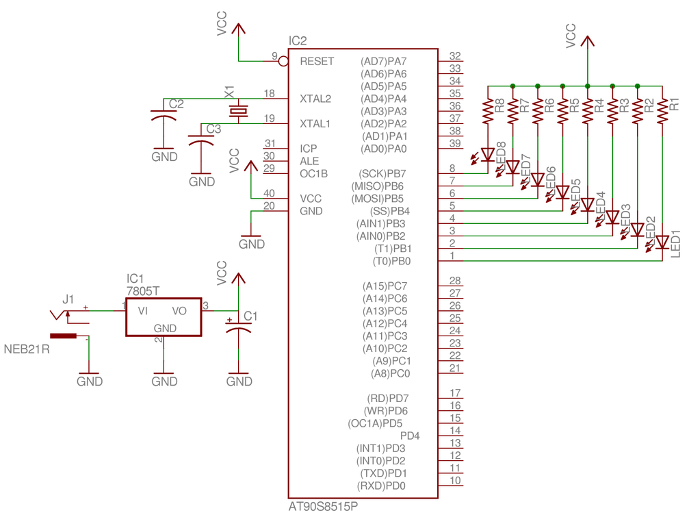
Figure 4. HelloAVR Program Test Circuit
For those using the STK500 development kit, simply connect PORTB to the eight onboard LEDs using the ten-wire cable (as illustrated in Figure 3), and watch das blinkenlights. You can set up your own test hardware by constructing the schematic shown in Figure 4, which connects LEDs with suitable limiting resistors such that each pin of PORTB can activate one by going low and sinking current.
You’ve seen the flashing LEDs? Congratulate yourself; you are ready to begin creating your own AVR designs and software. See Resources for loads of AVR-related information and projects. There’s almost no limit to what you can do.
Atmel shares a number of interesting project ideas through its AVR application notes, where it details implementation of stepper motor controllers, IR remote control receivers and transmitters and even an embedded Web server. One amazing project, ContikiOS (see Resources), distributes an open-source Internet-enabled, multitasking, graphical operating system that has been ported to the AVR and uses a version of the VNC server instead of a regular screen.
Enjoy experimenting with these versatile microcontrollers, be sure to share your discoveries and good luck building that robot horde!
Resources for this article: www.linuxjournal.com/article/7920.
Filed under: Artikel-artikel, Elektro banget, mikrokontroler_linux, Mikrokontroller | Tagged: linux | 4 Comments »


