Programming the AVR microcontroller with GCC, libc 1.0.4
![[Illustration]](https://i0.wp.com/www.linuxfocus.org/common/images2/article352/illustration.gif)
Abstract:
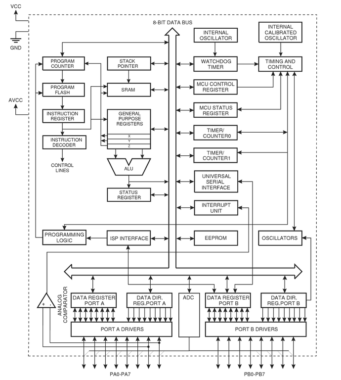
The AVR 8-Bit RISC microcontroller from Atmel is a very common microcontroller. This microcontroller is one chip with EEPROM, Ram, Analog to Digital converter, a lot of digital input and output lines, timers, UART for RS 232 communication and many other things.
The best is however that a complete programming environment is available under Linux: You can program this microcontroller in C using GCC.
I wrote already in March 2002 an article about the same subject. A lot of things have changed in the avr-libc development and the AT90S4433 microcontroller which I used in 2002 is no longer manufactured by Atmel. This is therefore an update of the March 2002 article. I will use libc-1.0.4 and the ATmega8 microcontroller.
This article shall be only an introduction and in a later series of articles we will again build interesting hardware but this time based on the ATmega8.
_________________ _________________ _________________
Introduction
Many people where interested in microcontroller programming after the article which I wrote in 2002. However this first step to get the development environment up and running is the hardest. If something does not work then you have absolutely no clue where the fault is. Programmer cable wrong?? Circuit faulty? Installation incorrect? Parallelport disabled in bios? Kernel modules for ppdev compiled wrong? There can be a lot of reasons why things don’t work. 
To make the entrance to the exciting world of microcontrollers easier shop.tuxgraphics.org offers now a bootable CD with a manual and the programmer hardware. All you need to do then is boot from this CD and everything is up and running. No software installation is required and nothing is modified on your local computer.
Even I use such a CD now for a while because the hardware I build often survives several generations of kernels and software installations on my PC. If I want later on to update some microcontroller software then I do not have to worry if the development environment on my Linux PC is still working. I just boot from the CD and it is up and running.
Independent of this CD I will explain the installation of the GCC avr development environment in the following paragraphs. If you have the CD from tuxgraphics then continue with chapter “A small test project”.
Software installation: What you need
To use the GNU C development environment you need the following software:
| binutils-2.15.tar.bz2 | Available from: ftp://ftp.gnu.org/gnu/binutils/ or any mirror. E.g: ftp://gatekeeper.dec.com/pub/GNU/binutils/ |
| gcc-core-3.4.2.tar.bz2 | Available from: ftp://ftp.gnu.org/gnu/gcc/ or any mirror. E.g: ftp://gatekeeper.dec.com/pub/GNU/gcc/ |
| avr-libc-1.0.4.tar.bz2 | The AVR C-library is available from: http://savannah.nongnu.org/projects/avr-libc/ |
| uisp-20040311.tar.bz2 | The AVR programmer software is available from: http://savannah.nongnu.org/projects/uisp |
We will install all the programs to /usr/local/avr. This is to keep the program separate from your normal Linux C compiler. Create this directory with the command:
    mkdir /usr/local/avr

You can add it already now to your PATH:
    mkdir /usr/local/avr/bin
    export PATH=/usr/local/avr/bin:${PATH}
Software installation: GNU binutils
The binutils package provides all the low-level utilities needed for building object files. It includes an AVR assembler (avr-as), linker (avr-ld), library handling tools (avr-ranlib, avr-ar), programs to generate object files loadable to the microcontroller’s EEPROM (avr-objcopy), disassembler (avr-objdump) and utilities such as avr-strip and avr-size.
Run the following commands to build and install the binutils :
tar jxvf binutils-2.15.tar.bz2
cd binutils-2.15/
mkdir obj-avr
cd obj-avr
../configure --target=avr --prefix=/usr/local/avr --disable-nls
make

# as root:
make install
Add the line /usr/local/avr/lib to the file /etc/ld.so.conf and run the command /sbin/ldconfig to rebuild the linker cache.
Software installation: AVR gcc
avr-gcc will be our C compiler.
Run the following command to build and install it:
tar jxvf gcc-core-3.4.2.tar.bz2
cd gcc-3.4.2

mkdir obj-avr
cd obj-avr
../configure --target=avr --prefix=/usr/local/avr --disable-nls --enable-language=c

make

# as root:
make install
Software installation: The AVR C-library
The C-library is quite stable now compared to the one I presented in March 2002.
Run the following command to build and install it:
tar jxvf avr-libc-1.0.4.tar.bz2
cd avr-libc-1.0.4
PREFIX=/usr/local/avr
export PREFIX
sh -x ./doconf
./domake

cd build
#as root:
make install
Software installation: The Programmer
The programmer software loads the specially prepared object code into the EEPROM of our microcontroller.
The uisp programmer for Linux is a very good programmer. It can be used directly from within a Makefile. You just add a “make load” rule and you can compile and load the software in one go.
uisp is installed as follows:
tar jxvf uisp-20040311.tar.bz2.tar
cd uisp-20040311
./configure --prefix=/usr/local/avr
make

# as root:
make install
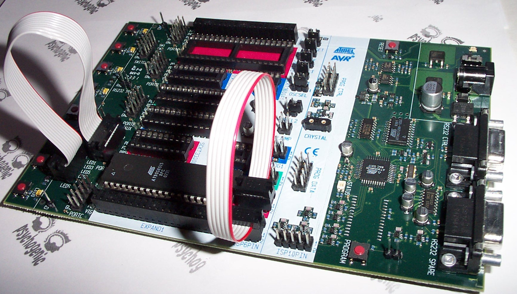
A small test project
We will start with a small test circuit which you can expand later on.
This circuit can also be used as a simple test environment for more complex hardware. You can easily test load software and attach sensors or measurement equipment.
Our test program as presented here will just cause a LED to blink.

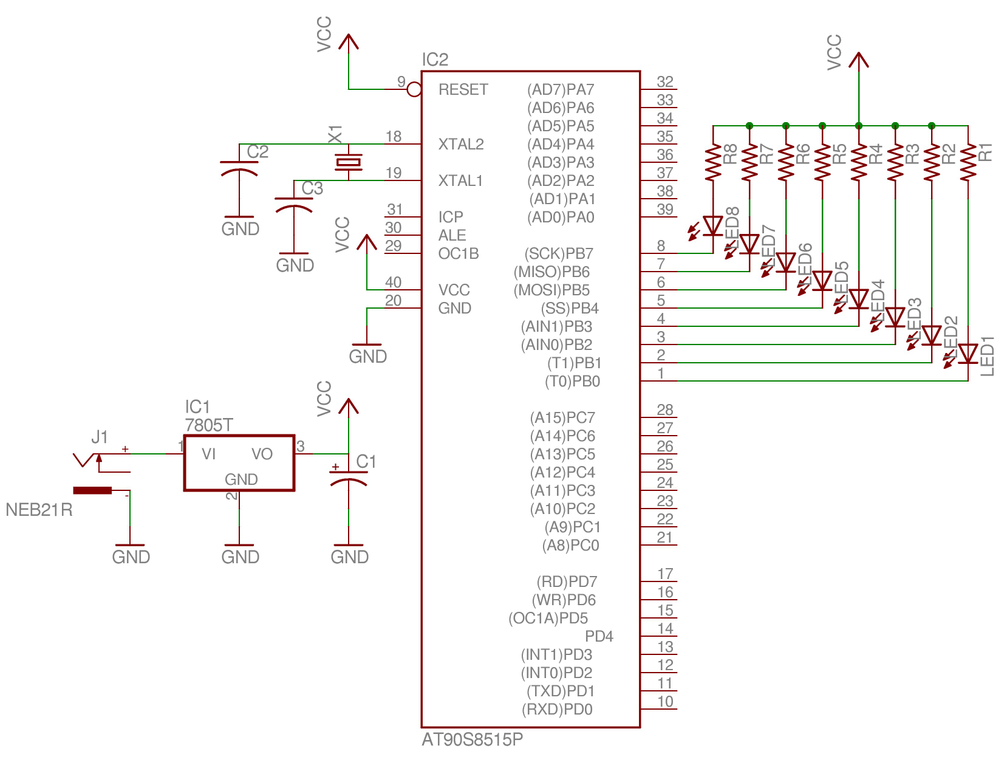
Needed Hardware
![[test circuit]](https://i0.wp.com/www.linuxfocus.org/common/images2/article352/avrm8ledtest_circuit.jpg)
You need the parts listed in the table below. Although it is a very common microcontroller it might not be available in every local radio shop but bigger distributors for electronic components like ( http://www.conrad.de (germany), http://www.selectronic.fr (france), digikey.com (US, CA), etc… have it in store).
The best place to get the microcontroller and the other parts is however: shop.tuxgraphics.org ;-).
| 1 x ATmega8 DIP version, Atmel 8 bit Avr risc processor. |
| 1 x 28 pin 7.5mm IC socket The 28 pin socket is a bit more difficult to get. Usually the 28 sockets are 14mm wide but we need a 7.5mm socket. |
| 1 x 10K resistor (color code: brown,black,orange) 1 x 1K resistor (color code: brown,black,red) 1 x 10uF electrolytic capacitor Some wires 1 x LED matrix board |
| The following is needed for the programmer (not needed if you get the “Linux AVR programming kit” from tuxgraphics): 1 x DB25 connector to plug into the parallel port. Any kind of 5 pin connector/socket for the programmer. I recommend to use precision strip connectors (similar to IC sockets) and break 5 pins off. 1 x 220 Ohm resistor (color code: red,red,brown) 2 x 470 Ohm resistor (color code: yellow,purple,brown) |
In addition to the above parts you need a 5V electronically stabilized DC power supply or you can use a 4.5V battery as power supply.
You have probably noticed that we do not need a crystal. This is because the ATmega8 has now a build-in oscilator. This oscilator can be used when accurate timing is not an issue. However if you want to build precise measurement equipment or you want to use the UART/RS232 interface then you will need a crystal. Which type of oscilator is used can be defined via fuse bits which you can modify with the programmer. By default (factory setting) the internal 1Mhz oscilator is active.
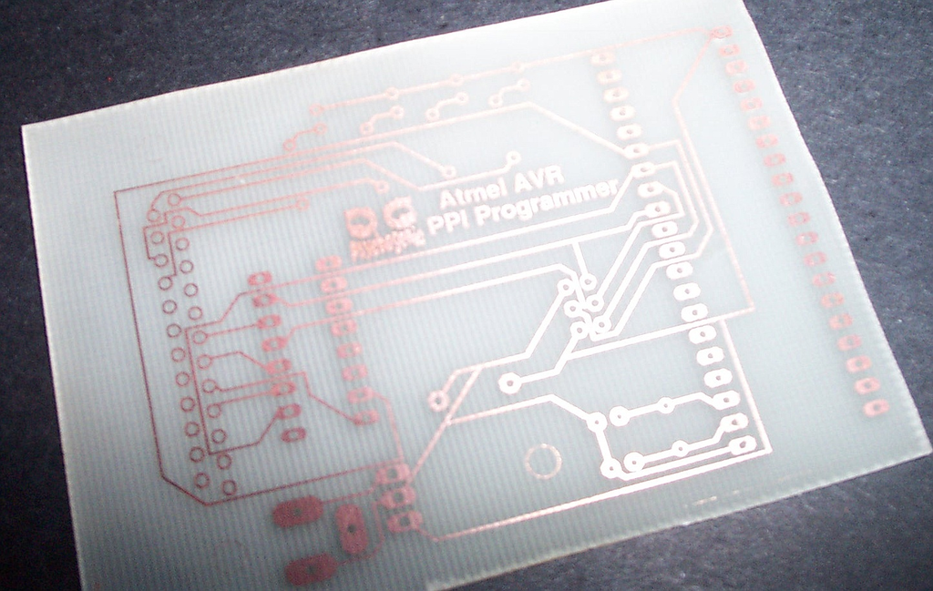
Building the programmer hardware
The AVR microcontrollers allows for in circuit programming (ISP). ![[Linux AVR programmer]](https://i0.wp.com/www.linuxfocus.org/common/images2/article352/avr_programmer.jpg)
That is: you do not need to remove the microcontroller form the board to program it. You will see that you can get different programmer hardware from 50-150 Euro. However with Linux running it is also possible to build a very simple programmer that does the job. You need a free parallel port on your computer and the following cable.
Note that this is an improved programmer compared to the one presented in the March 2002 article. We build the protection resistors into the programmer. This will then save some space and parts on the circuit board. The wiring for the programmer cable has to be as follows:
| pin on pcb | pin on AVR | protection resistor | Pin on parallel port |
|---|---|---|---|
| 5 | Reset (1) | — | Init (16) |
| 4 | MOSI (17) | 470 Ohm | D0 (2) |
| 3 | MISO (18) | 220 Ohm | Busy (11) |
| 2 | SCK (19) | 470 Ohm | Strobe (1) |
| 1 | GND | — | GND (18) |
The cable should not be longer than 70cm.
The protection resistors can be build into the connector as show on the picture on the right.
Writing software
The Atmeag 8 can be programmed in plain C with the help of gcc. To know some AVR assembler can be useful but it is not needed.
The AVR libc comes with an avr-libc-user-manual-1.0.4.pdf (1139921 bytes) which documents all functions available in C. From Atmel’s website, (www.atmel.com, go to: avr products -> 8 bit risc-> Datasheets), you can download the complete data sheet. It describes all the registers and how to use the CPU.
One thing to keep in mind when using a microcontroller is that it has only a few bytes of Ram. That means you must not declare large data structures or strings. Your program should not use deeply nested function calls or recursion.
Much better than all theory is a real example. We will write a program that causes our LED to blink in 0.5 seconds intervals. Not very useful but very good to get started.
The avr-libc has changed a lot. Previously you did set a bit on a port with sbi and you cleared it with cbi. Now those functions are deprecated. First I present the “good old way”:
    /* defines for future compatibility */
    #ifndef cbi
    #define cbi(sfr, bit) (_SFR_BYTE(sfr) &= ~_BV(bit))
    #endif
    #ifndef sbi
    #define sbi(sfr, bit) (_SFR_BYTE(sfr) |= _BV(bit))
    #endif

    void main(void)
    {
          /* INITIALIZE */
          /* enable PC5 as output */
          sbi(DDRC,PC5);

          /* BLINK, BLINK ... */
          while (1) {
                /* led on, pin=0 */
                cbi(PORTC,PC5);
                delay_ms(500);
                /* set output to 5V, LED off */
                sbi(PORTC,PC5);
                delay_ms(500);
          }
    }
The following example does exactly the same but uses the new syntax:
    void main(void)
    {
          /* INITIALIZE */
          /* enable PC5 as output */
          DDRC|= _BV(PC5);

          /* BLINK, BLINK ... */

          /* PC5 is 5 (see file include/avr/iom8.h) and _BV(PC5) is 00100000 */
          while (1) {
                /* led on, pin=0 */
                PORTC&= ~_BV(PC5);
                delay_ms(500);
                /* set output to 5V, LED off */
                PORTC|= _BV(PC5);
                delay_ms(500);
          }
    }
The above code snipet shows how simple it is to write a program. You see only the main program, the delay_ms function is included in the full listing (avrm8ledtest.c). To use pin PC5 as output you need to set the PC5 bit in the data direction register for port C (DDRC). After that you can set PC5 to 0V with the function cbi(PORTC,PC5) (clear bit PC5) or to 5V with sbi(PORTC,PC5) (set bit PC5). The value of “PC5” is defined in iom8.h which is included via io.h. You don’t have to worry about it. If you have already written programs for multi user / multi tasking systems such as Linux you know that one must never program a non blocking endless loop. This would be a waste of CPU time and slow the system very much down. In the case of the AVR this is different. We don’t have several tasks and there is no other program running. There is not even an operating system. It is therefore quite normal to busy loop forever.
Compiling and loading
Before you start make sure that you have /usr/local/avr/bin in the PATH. If needed edit your .bash_profile or .tcshrc and add:
export PATH=/usr/local/avr/bin:${PATH} (for bash)
setenv PATH /usr/local/atmel/bin:${PATH} (for tcsh)
We use the parallel port and uisp to program the AVR. Uisp uses the ppdev interface of the kernel. Therefore you need to have the following kernel modules loaded:
    # /sbin/lsmod
    parport_pc
    ppdev
    parport
Check with the command /sbin/lsmod that they are loaded otherwise load them (as root) with:
    modprobe parport
    modprobe parport_pc
    modprobe ppdev
It is a good idea to execute these commands automatically during startup. You can add them to a rc script (e.g for Redhat /etc/rc.d/rc.local).
To use the ppdev interface as normal user root needs to give you write access by once running the command
chmod 666 /dev/parport0
Make as well sure that no printer daemon is running on the parallel port. If you have one running then stop it before you connect the programmer cable. Now everything is ready to compile and program our microcontroller.
The package for our test program (avrm8ledtest-0.1.tar.gz) includes a make file. All you need to do is type:
make
make load
This will compile and load the software. I will not go into the details of all the commands. You can see them in the Makefile and they are always the same. I can my self not remember all of them. I just know that I need to use “make load”. If you want to write a different program then just replace all occurrences of avrm8ledtest in the Makefile with the name of your program.
Some interesting binutils
More interesting than the actual compilation process are some of the binutils.
Those utilities have however not really changed since March 2002. Take a look at the “Some interesting binutils” chapter in article231, March 2002.
Ideas and suggestions
The ATmega8 is compatible to the AT90S4433 for most uses. You need to program the fuse bits to use the external oscilator and the previously presented hardware might work with possibly minor changes. Unfortunatley I have not had time yet to re-test all circuits for the ATmega8. If you want to be on the save side then use the AT90S4433 for the old articles. If you don’t mind to troubleshoot and solve problems then try the ATmega8 with the old articles/circuits.
Here is a list of those previous hardware articles:
- A LCD control panel for your Linux server
- A microcontroller based DC power supply
- Frequency counter 1Hz-100Mhz with LCD display and RS232 interface
- Linux USB LCD display with watchdog and buttons
- Building an autonomous light finder robot
Note: the programmer presented here includes already the protection resistors which were build into the circuit board in the older hardware articles. To use the new programmer with the old boards you will just need to replace the protection resistors on the board by wires.
Atmel provides an application note “AVR081: Replacing AT90S4433 by ATmega8” which lists all the incompatibilities: at90s4433_to_atmega8.pdf (101343 bytes)
References
- Pascal Stang’s AVRlib: http://www.procyonengineering.com/avr/avrlib/index.html or http://hubbard.engr.scu.edu/embedded/avr/avrlib/
- the tavrasm assembler for Linux: www.tavrasm.org
- All software and documents mentioned in this article
- The atmel website: www.atmel.com
- Electronic pages from the tuxgraphics shop: shop.tuxgraphics.org
(Here you can get the Linux AVR programming CD, kits and microcontrollers)
Filed under: Artikel-artikel, avr, Elektro banget, linux, mikrokontroler_linux, uclinux | Tagged: microcontroller | 1 Comment »